My Transverter for 2.3Ghz is built into a Yaesu FT736R. These excellent radios are now so cheap on the second hand market. That they make a neat compact cost effective way of housing a transverter.
Becoming a stand alone unit cutting down on inter wiring . The Radio supplies the power and houses the transverter, sequencing for amplifiers and preamp. (more about the neat sequencing later).
The transverter is from SSB Electronics with a 2m IF. I also have a SG Labs transverter with 70cm IF for portable working.
There are two IF Taps. 1st IF and transverter IF 144MHz for full band, using HUP panadater buffer boards

Sequencer – Installing the W6PQL sequencer in the Yaesu 736R (Credit to WA7TZY Borrowed from his site click here )
The 736R presents some interesting challenges when trying to use it in conjunction with a high power amplifier and preamp combination. The basic problem is that some of the 736R timing anomalies can lead to hot switching issues with the power amp and preamp. This can potentially ruin relays, trip protective circuits (if there), blow pre-amps by inserting backwards going RF and in some severe cases even the loss of the power devices themselves.
One potential solution to this problem is to install a W6PQL (PQL) sequencer in the 736 and delay any possibility of undesired output until all of the relays have had a chance to settle in their switched state. I chose the PQL sequencer as it is available from W6PQL in surface mount (SMT) kit form, uses currently available parts, is well engineered and is small.
A word of caution. Building the PQL sequencer and installing it requires familiarity and skill with employing surface mount construction and anti-static procedures. It also takes a modicum of skill in dealing with delicate circuitry and components. If you are all thumbs or don’t have any experience, proceed very, very carefully.
The first step is to obtain the PQL sequencer and construct and test it. W6PQL provides ample circuit diagrams and layouts to accomplish this. If you have SMT experience, this step can be accomplished in one evening. Remember to use anti-static procedures. Successfully completing the construction and testing of the PQL sequencer is also a good guide as to whether or not you should proceed. If you can not make the sequencer, perhaps it is a good idea not to open the radio…hi. Edit: (VHF Design also sell a ready made sequencer based on this one with the addition of 12v switching for a preamp)
Having the sequencer successfully completed and tested , it is now time to install it in the 736R. Before proceeding, it is a good idea to have copies of the Yaesu operators and service manuals for the 736R to refer to for opening the unit and locating the components. Again, use anti-static procedures! First carefully remove the top cover and internal speaker from the 736R. Put these in a safe place for now. Proceed to remove the front panel lock screws (see service manual) on each side and tilt the front panel forward. Also remove the two screws that hold the audio output board at the top corners so that it can be gently moved for the punching operation that will mount the sequencer board. The controller board screws must also be removed and the controller board tilted forward to make room for the punching tool as well as the small operation that must be performed on the controller board.
The sequencer board can be conveniently mounted in the open space just to the left of the audio output board (see photo of sequencer) as viewed from the front of the unit. Edit: (Or as I did in the space of an uninstalled band module along with a transverter)


Mount the sequencer board using a pair of 3/8×4/40 screws, heads to the front of the unit and covered with electrical tape, and 4/40 nuts used as spacers between the board and the chassis. Slide the sequencer board over the screws and retain it in place with two more 4/40 nuts. Run a wire (I used red) from the +12 line (red wire) in the left rear of the transceiver to the +12 input of the sequencer. The sequencer is returned to ground by the 4/40 mounting screws. You will use the “event 1” and “event 4” terminals on the sequencer. Now is a good time to solder the 30k ohm (any value 30k to 47k will work) resistor to the pad labelled “event 4” on the sequencer board along with the 2N4123 or equivalent transistor (see sequencer schematic and photo at left). Now is also a good time to carefully set the audio output board in its lower grooves and reinstall the two screws that hold it. Be sure that the board is set in its lower groves before fastening.

Locate the orange wire (either pin 2 or pin 3 will work depending on accessibility) that comes from the TX board and goes to the “drive pot”. There should be a 3.3k resistor between this wire and the 8 volt supply on the TX board. Verify this! If the 3.3k resistor is not there, there will be smoke! Now cut the orange wire near the sequencer board, strip both ends and solder to the unterminated 2N4123 collector. The diagram to the left shows the drive pot connection.
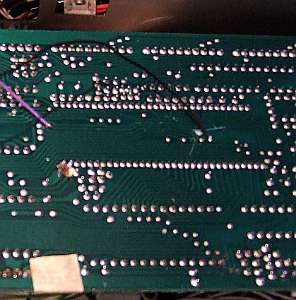

The next step involves a little surgery to the controller board. Remember anti-static procedures should be rigorously used here. Pin 24 of the microprocessor is connected to a 10k pull up resistor to 5 volts. The remainder of the circuit is connected to the PTT buss. The PTT buss must be isolated from pin 24 on the microprocessor and the 10k pull up resistor. This trace can be conveniently and carefully severed on the reverse side of the controller board just under the microprocessor (see controller board photo at left). The cut can be seen about 1/4” to the left and slightly above where the small black wire is soldered to the via. It is the white spot with a pair of lines pointing to it. There are via pads conveniently located either side of the severing point that can be used to attach the last two wires to the sequencer. Run a thin wire (black in my case) from the “event 1” terminal on the sequencer to the via closest to pin 24 on the processor. Run a second wire (violet in my case) from PTT on the sequencer to the via on the opposite side of the cut (see photo and schematic). The sequencer can be removed if desired by soldering a wire from via to via and bridging the cut. Carefully reset the controller board in its mounting grooves and reinsert the screws that secured the top of the controller to the chassis. Carefully swing the front panel back into the vertical position and secure it. It is time to test the unit. In this configuration the “event 1” LED will be on continuously. This is not a problem as there is a tiny amount of current flowing from the +12 through the LED through the pull up to the +5 in the off state. If this bothers you, an easy solution is to remove R26 from the sequencer board.
Set the pot on the sequencer to mid position, terminate the radio output with a PEP reading watt meter and a 50 ohm load, and plug a set of phones into the front panel jack. If you have done everything correctly, the radio should sequence providing a delay between PTT activate and the application of voltage to the drive pot, which will enable the output. Conversely, when the PTT is deactivated there will be a quick denial of voltage to the drive pot, which will suppress any output before the relays are released. With the mic gain set to 0, there should be no indication in the SSB mode when the unit is keyed. Switch the unit to the CW mode, close the key and put the watt meter in the CW mode. Turn the unit on with the PTT and you should see a slight delay between activation of the PTT and the CW output.
Congratulations, you have installed the sequencer! You may adjust the sequencer timing by varying the pot on the sequencer board. An oscilloscope is really useful here. Reassemble the 736R top cover and internal speaker and enjoy operation without fear of damaging relays, pre-amps or output devices. This, of course, assumes that your power amps and pre-amps are open circuit stable (unconditionally stable). If they are not, all bets are off and you might want to bring event 2 and 3 terminals out to the rear panel of the 736R to facilitate switching the B+ to the power amp after the relays are thrown.
A few words about arcing and stability are in order. The E/I curve of an arc has a negative slope and, as such can present a negative impedance to the output devices of a transmitter. This depending on conditions surrounding the amplifier can be very tough on output devices, the claims of ruggedness by the manufacturer aside. Unconditional stability is another often overlooked trait of an amplifier. Today, the bulk of amplifiers designed for commercial service are unconditionally stable. For example, I can not imagine a “hot swappable” design for broadcast service without serious consideration paid to unconditional stability. Unfortunately a number of designs for ham radio applications have not been so thoroughly designed and tested. If you are not sure about the equipment you are using, you would be well advised to use events 2 or 3 to control power to the amplifier or, as an alternative, use a second sequencer at the amplifier timed to operate within the timing of the first sequencer.
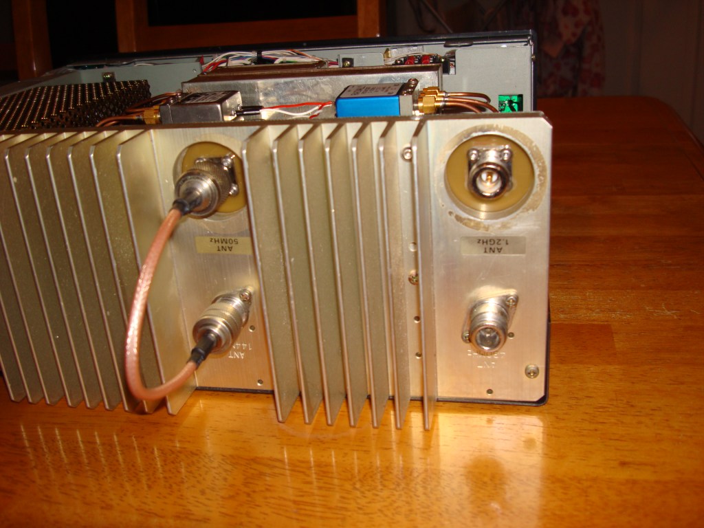
The Amplifier
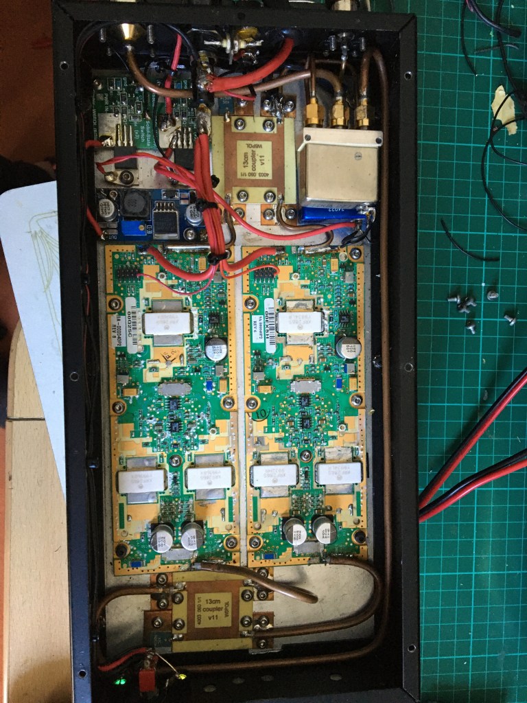
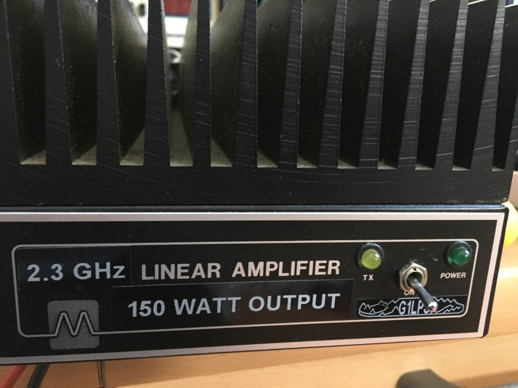
built into an old microwave modules case

The Antenna
Antenna is a Tonna F9FT 25 element With wave guide feed and Khune electronics preamp.


You must be logged in to post a comment.