24GHz building blocks
A transverter for narrowband and ATV/DATV
My self and Rob M0DTS have been experimenting with 24GHz with good results. Rob had built a transverter for the band from surplus equipment and I began with a solfan type head from a security motion detector 5mw output power. This was driven with a Bob Platt gunmod 2 board modified for 5v to the gun diode and a horn antenna.
With the horn antenna on my mast. Rob could receive my TV signals both at home 28km and at his portable site 54km P5!.
This low power experimentation encouraged me to look for a transverter with more power output and RX capability, A search for the unit Rob had built from drew a blank. We then found on eBay a plentiful and cheap supply of units from Israel operating on 27 – 29GHz. made by Broadern.
Broadern-RF-Microwave-Transceiver-ED-0612-2 27.35-29.45GHz TX-RX WR28-SMA
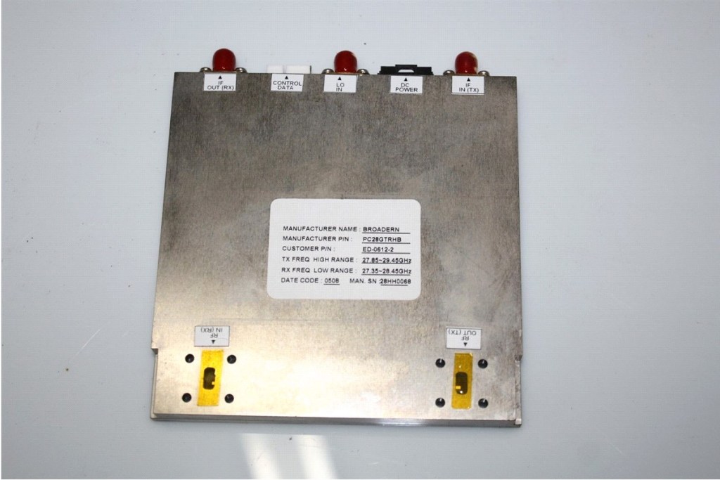
We both purchased one to play with not knowing if they could be easily converted. They have a 2x multiplier and we planned to use 23cm as the IF.
Rob the RF guru in our group did some investigation and came up with the following solution to drop the frequency in to the amateur band.
TX Modification
1 layer of Kapton tape on the Ceramic Tx Filter, then a smaller length of sticky copper tape on top of that. Tuning for max output was achieved with a copper tab on output of the device before the filter.
Tx power was measured using a diode detector rated 18GHz. It was confirmed that the power was in the correct band with a filter tuned to 24GHz. Expect >300mW without tweaking.
These units require the tiniest sniff of RF to drive to full power which is not very practical in operation. We have removed all TX drive stages apart from the 6dB attenuator right before the mixer. This was done by connecting the the tx in sma with coaxial cable directly to the attenuator, 10mW input = 500mW output on our units. There ia a pi attenuator immediately after the 6db attenuator that can be bypassed if your low on drive.
This came about by accident on the first unit because a driver stage was killed in the mod process with +8v instead of +5v supply rail as some other info suggests on the internet. But 10mw drive really is more comfortable to operate and is a good match for many of our TV transmitters both analogue and digital.
Connection to mixer to allow 10mw drive (yellow connection)

TX and RX mods

CAUTION!!! BE EXTREMELY CAREFUL NOT TO BREAK ANY WIRE BONDS, SOME LOOP OVER THE RF TRACKS LEADING INTO MMICS.

MICROSCOPE VIEW OF TINY WIRE BONDS ON DEVICE AND OVER TRACKS . INCLUDING A DETAILED VIEW OF THE ADDED COPPER TAB.
RX Modification
The Rx Filter has 2 layers of kapton tape across the full length of the filter elements.
Rx Noise figure is in the 10dB region (We can’t measure that accurately) you can easily install a pre-amplifier on these if you wish to work any real dx… Rob built the DB6NT LNA. and I’m opting for the DG0VE ready built LNA with 20db gain and 2.3NF
The LO
The Lo unit we chose is the Elcom DFS1201 11.2 to 12GHz Oscillator. A common one widely used in microwave projects so rather than cover it here in detail I will point interested parties to this link. http://g4fre.com/dfs1201.htm for a description of how it works.
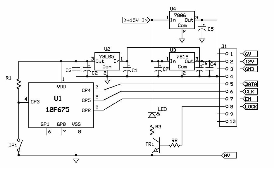
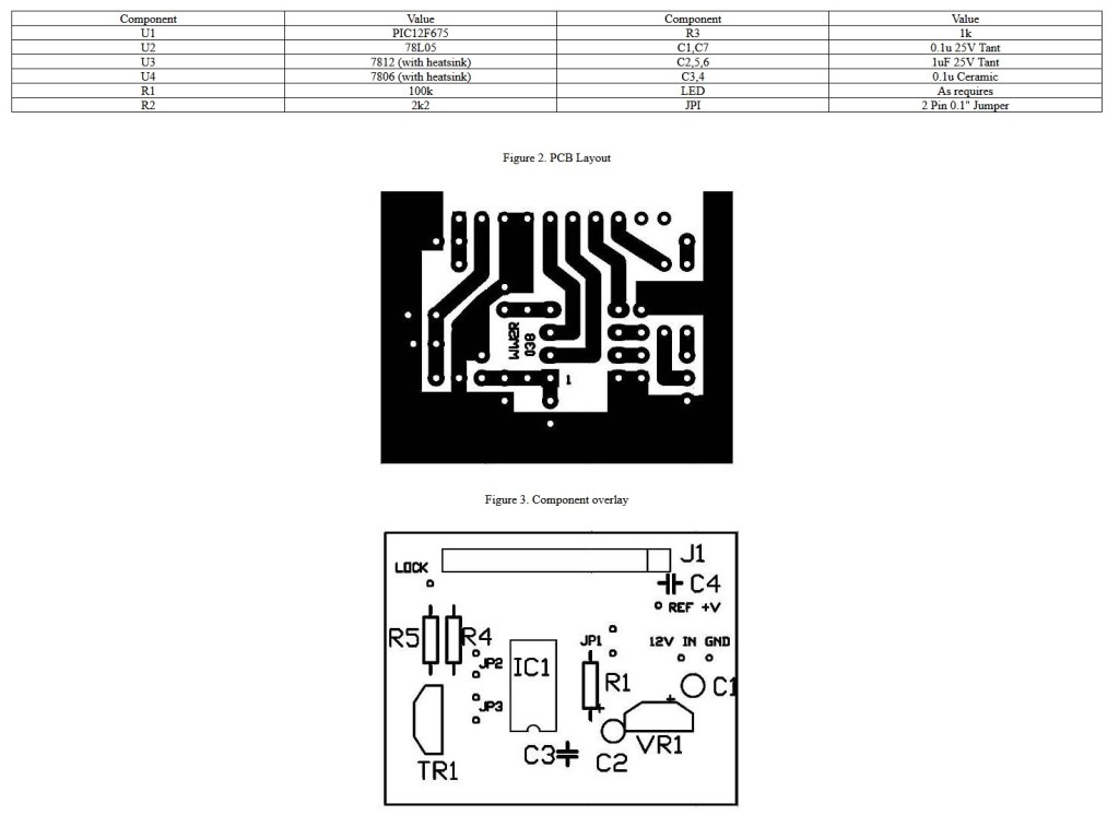
To set the frequency of the Elcom unit simply construct the circuit below and Program a 12F675 pic chip. Then plug the circuit into the socket on the oscillator. No internal modifications are needed for this unit.
The 12F675 HEX code for the LO can be found here Dfs1201_11400.zip
The LO we used was 11.4GHz (11.4 x2 + 1.2GHz =24Ghz)
Circuit for Setting the frequency on the LO

PTT Sequencing
Ground the PTT line to key TX

Power supplies
Cheap DC-DC stepup and step down converters were used to provide the various voltages required for the transciver unit. +12v, +10v, +5v (and in my case +24v as a 24v sma relay was used) The -12v negative voltage was generated using a LMC7660IN. DC-DC converters can also be modified to give negative voltage. See http://www.m0dts.co.uk/?tag=Mods for how to do this. (Negative voltage DC-DC converters are also available on eBay)
Boxing and plumbing it together
The two units were mounted either side of a 12mm thick block of aluminium for heat-sink and fit into a die-cast box. wave guide transitions to sma were used (wr28 for the tx and rx ports and wr42 for the antenna port. All interconnections were made in hardline. For switching an sma relay rated to 26ghz. An XLR connector was used to connect power, PTT and power detect cables.
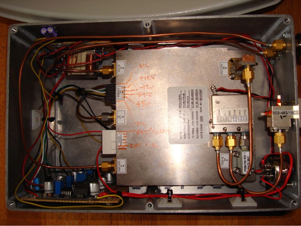
DC Power connections
1. Not Connected
2. +10v
3. -12v
4. GND
5. +5V
6. Not Connected
Control Data
1. PTT
6. Power Detect
Wave guide transitions to sma for these frequencies can be expensive. Both Rob and myself had to resort to making some after weeks of searching for cheap ones. This was simple to do I used a hot plate (cooker ring) to get the heat in and soldered a copper plate on the open end of a flanged straight waveguide cut to length. The plate was wired to keep it in place while soldering. It was then filed and dressed up after cooling. Drill the hole for the sma before soldering so that it can be dressed clean on both sides of the hole. Sma centre pin protrudes 2.2mm into the waveguide and is 2.5mm from the end wall.
This is not presented as a finished project but more for information about what we have been doing and the cheap building blocks we used to achieve access to the 24GHz band.
I have also found a very similar solution to the one we created. This can be found here. http://www.sydneyHYPERLINK “http://www.sydneystormcity.com/24GHz.htm”sHYPERLINK “http://www.sydneystormcity.com/24GHz.htm”tormcity.com/24GHz.htm using a similar harder to find transceiver and the Elcom oscillator.
Have fun experimenting Terry G1LPS

You must be logged in to post a comment.